接口信息Connector Information
本章给出 IC-7300 全部接口的引脚定义与规格:13 针 ACC 插座的逐针名称、说明与电气参数,OPC-599 ACC 转接线的引脚分配,8 针话筒插座的引脚定义,以及外接键盘的电路与设置方法。本章还逐一说明 KEY、EXT-SP、REMOTE、ALC、SEND、PHONES 各插孔和 DC 电源插座的用途、阻抗与控制电压。引脚表中的数值是与其他设备连接和自制接口线时的唯一依据,请务必对照实物核验。
This chapter gives the pin definitions and specifications of all of the IC-7300 connectors: the pin-by-pin names, descriptions and electrical specifications of the 13-pin ACC socket, the pin assignments of the OPC-599 ACC conversion cable, the pin definitions of the 8-pin microphone connector, and the circuit and settings for the external keypad. The KEY, EXT-SP, REMOTE, ALC, SEND and PHONES jacks and the DC power socket are also described, with their impedances and control voltages. The values in the pin tables are the reference for connecting other equipment and for making your own interface cables.
18-2ACC 插座ACC socket
用于连接外接设备或 PC,以便控制外接设备,或由外部控制本收发信机。
Connects to external equipment or a PC to control the external unit or to control the transceiver.
| 引脚号PIN No. | 名称NAME | 说明DESCRIPTION | 规格SPECIFICATIONS |
|---|---|---|---|
| 1 | 8 V | 稳压 8 V 输出。 (用作波段电压的基准电压。)Regulated 8 V output. (Used as the reference voltage for the band voltage.) | 输出电压:8 V ±0.3 V 输出电流:小于 10 mAOutput voltage: 8 V ±0.3 V Output current: Less than 10 mA |
| 2 | GND | 接地。Connects to ground. | —— |
| 3 | SEND*1 | 输入/输出引脚。 由外接设备控制本收发信机。此引脚接地时,本收发信机进入发射状态。 发射时该引脚为低电平。Input/output pin. An external unit controls the transceiver. When this pin goes to ground, the transceiver transmits. The pin goes low when the transceiver transmits. | 输入电压(RX):2.0 至 20.0 V 输入电压(TX):-0.5 至 +0.8 V 电流:最大 20 mA 输出电压(TX):小于 0.1 V 电流:最大 200 mAInput voltage (RX): 2.0 to 20.0 V Input voltage (TX): -0.5 to +0.8 V Current flow: Maximum 20 mA Output voltage (TX): Less than 0.1 V Current flow: Maximum 200 mA |
| 4 | BDT | 未使用。Not used. | —— |
| 5 | BAND | 波段电压输出。 (随所选的业余波段而变化)Band voltage output. (Varies with the selected amateur band) | 输出电压:0 至 8.0 VOutput voltage: 0 to 8.0 V |
| 6 | ALC | ALC 电压输入。ALC voltage input. | 输入电平:-4 至 0 V 输入阻抗:大于 3.3 kΩInput level: -4 to 0 V Input impedance: More than 3.3 kΩ |
| 7 | NC | —— | —— |
| 8 | 13.8 V | 电源开启时输出 13.8 V。13.8 V output when power is ON. | 输出电流:最大 1 AOutput current: Maximum 1 A |
| 9 | TKEY | 未使用。Not used. | —— |
| 10 | FSKK | 控制 RTTY 键控。Controls RTTY keying. | 高电平:大于 2.4 V 低电平:小于 0.6 V 输出电流:小于 2 mAHigh level: More than 2.4 V Low level: Less than 0.6 V Output current: Less than 2 mA |
| 11 | MOD | 调制器输入。Modulator input. | 输入阻抗:10 kΩ 输入电平:100 mV rms*3Input impedance: 10 kΩ Input level: 100 mV rms*3 |
| 12 | AF/IF (IF=12 kHz)*2 | 固定 AF 检测器输出,或接收中频(12 kHz)信号输出。Fixed AF detector or receive IF (12 kHz) signal output. | 输出阻抗:4.7 kΩ 输出电平:100 ~ 300 mV rms*4Output impedance: 4.7 kΩ Output level: 100 ~ 300 mV rms*4 |
| 13 | SQL S | 静噪输出。静噪开启时接地。Squelch output. Grounded when the squelch opens. | SQL 开启:小于 0.3 V/5 mA SQL 关闭:大于 6.0 V/100 μASQL open: Less than 0.3 V/5 mA SQL closed: More than 6.0 V/100 μA |
说明 NOTENOTE
*1 当 SEND 端子控制的是继电器等感性负载时,反电动势可能造成故障或损坏收发信机。为防止此情况,建议在电路的负载侧并联一个开关二极管(例如 1SS133)以吸收反电动势。加上二极管后,继电器动作可能出现延时,使用前请务必确认其开关动作正常。
*2 可在 CONNECTORS 设置屏幕的 "ACC/USB Output Select" 项目中更改引脚 12 的设置。若设为 IF,收发信机将从 [ACC] 输出 12 kHz 中频信号,此时可用装在 PC 上的应用软件接收机收听 DRM 广播。
*3 可在 CONNECTORS 设置屏幕的 "ACC MOD Level" 项目中更改输入电平(见 12-9 节)。100 mV rms 对应 50%(默认)设置。
*4 可在 CONNECTORS 设置屏幕的 "ACC/USB AF Output Level" 项目中更改输出电平(见 12-9 节)。约 200 mV rms 对应 50%(默认)设置。
*1 When the SEND terminal controls an inductive load, such as a relay, a counter-electromotive force can malfunction or damage the transceiver. To prevent this, we recommend adding a switching diode, such as an 1SS133, on the load side of the circuit to absorb the counter-electromotive force. When the diode is added, a delay in relay switching may occur. Be sure to check its switching action before operating.
*2 You can change the pin 12 setting in the "ACC/USB Output Select" item on the CONNECTORS set screen. If the pin is set to IF, the transceiver outputs a 12 kHz IF signal from [ACC]. In that case, you can listen to the DRM broadcast with the application software receiver that is installed into your PC.
*3 You can change the input level in the "ACC MOD Level" item on the CONNECTORS set screen. (p. 12-9) 100 mV rms is at the 50% (default) setting.
*4 You can change the output level in the "ACC/USB AF Output Level" item on the CONNECTORS set screen. (p. 12-9) Approximately 200 mV rms is at the 50% (default) setting.
| 引脚号PIN No. | 名称NAME | 线色Color |
|---|---|---|
| ① | 8 V | 棕色brown |
| ② | GND | 红色red |
| ③ | SEND | 橙色orange |
| ④ | BDT | 黄色yellow |
| ⑤ | BAND | 绿色green |
| ⑥ | ALC | 蓝色blue |
| ⑦ | NC | 紫色purple |
| ⑧ | 13.8 V | 灰色gray |
| ⑨ | TKEY | 白色white |
| ⑩ | FSKK | 黑色black |
| ⑪ | MOD | 粉色pink |
| ⑫ | AF/IF | 浅蓝色light blue |
| ⑬ | SQL S | 浅绿色light green |
线色指随机附带电缆的线芯颜色。
Color refers to the cable strands of the supplied cable.
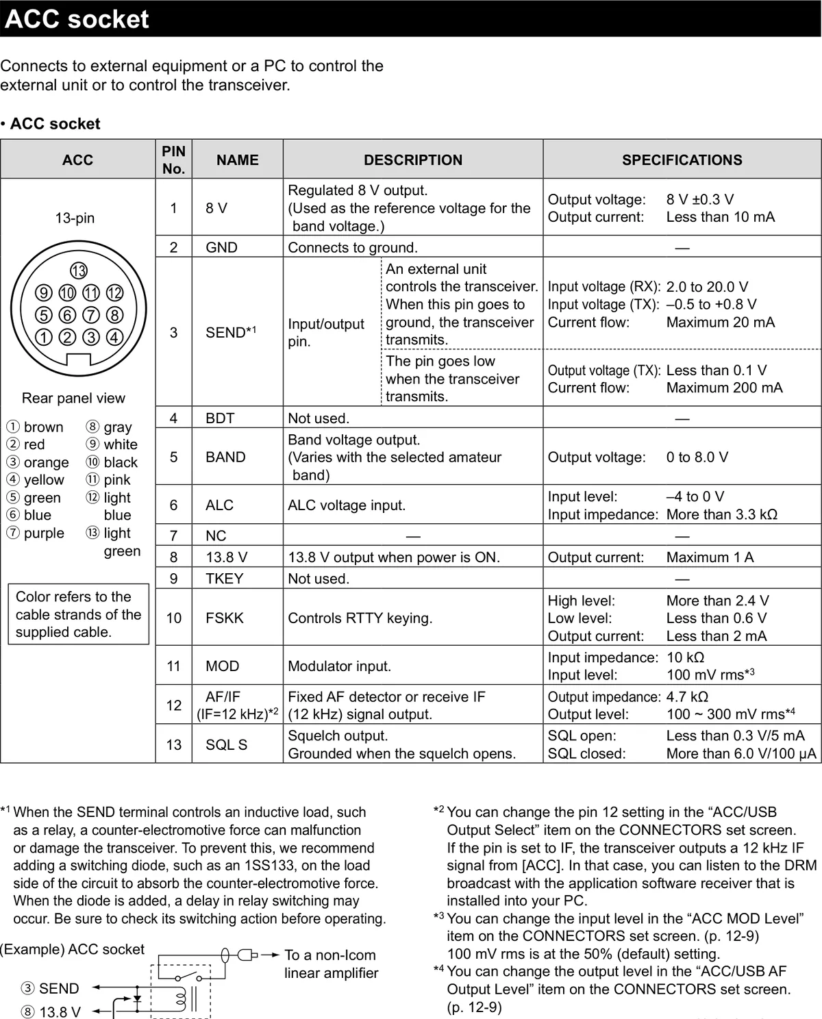
ACC 插座连接示例:③ SEND 与 ⑧ 13.8 V 经带开关二极管的继电器连接到非 Icom 线性放大器。
Example ACC socket circuit: ③ SEND and ⑧ 13.8 V are connected through a relay with a switching diode to a non-Icom linear amplifier.
火腿经验 HAM TIPHAM TIP
玩数字模式(JT-65/FT8/PSK31)必须选 DATA 模式(USB-D/FM-D 等),否则话筒音频会串进去、DATA MOD 也没路由;再用 ACC 的 [DATA] 相关引脚(MOD/AF)或 USB 声卡接电台。ACC 的 MOD 输入电平默认 100 mV rms,可按需在 SET > Connectors 里调整。
To work digital modes (JT-65/FT8/PSK31) you MUST select a DATA mode (USB-D/FM-D, etc.), otherwise the microphone audio gets mixed in and DATA MOD is not routed; then connect the radio through the ACC [DATA] pins (MOD/AF) or a USB sound card. The default ACC MOD input level is 100 mV rms and can be adjusted in SET > Connectors.
火腿经验 HAM TIPHAM TIP
RTTY 玩 FSK 需接 ACC 引脚 10(FSKK)做直频键控,AFSK 走声卡;FSK 方式更干净,不受声卡采样率影响。若用 OPC-599 转接线,FSK 信号走 ACC 1 的引脚 1。
For RTTY FSK operation, connect to ACC pin 10 (FSKK) for direct frequency keying; AFSK goes through the sound card. FSK is cleaner and is not affected by the sound card sample rate. When using the OPC-599 adapter cable, the FSK signal is on pin 1 of ACC 1.
18-3OPC-599 ACC 转接线引脚分配OPC-599 ACC conversion cable pin assignments
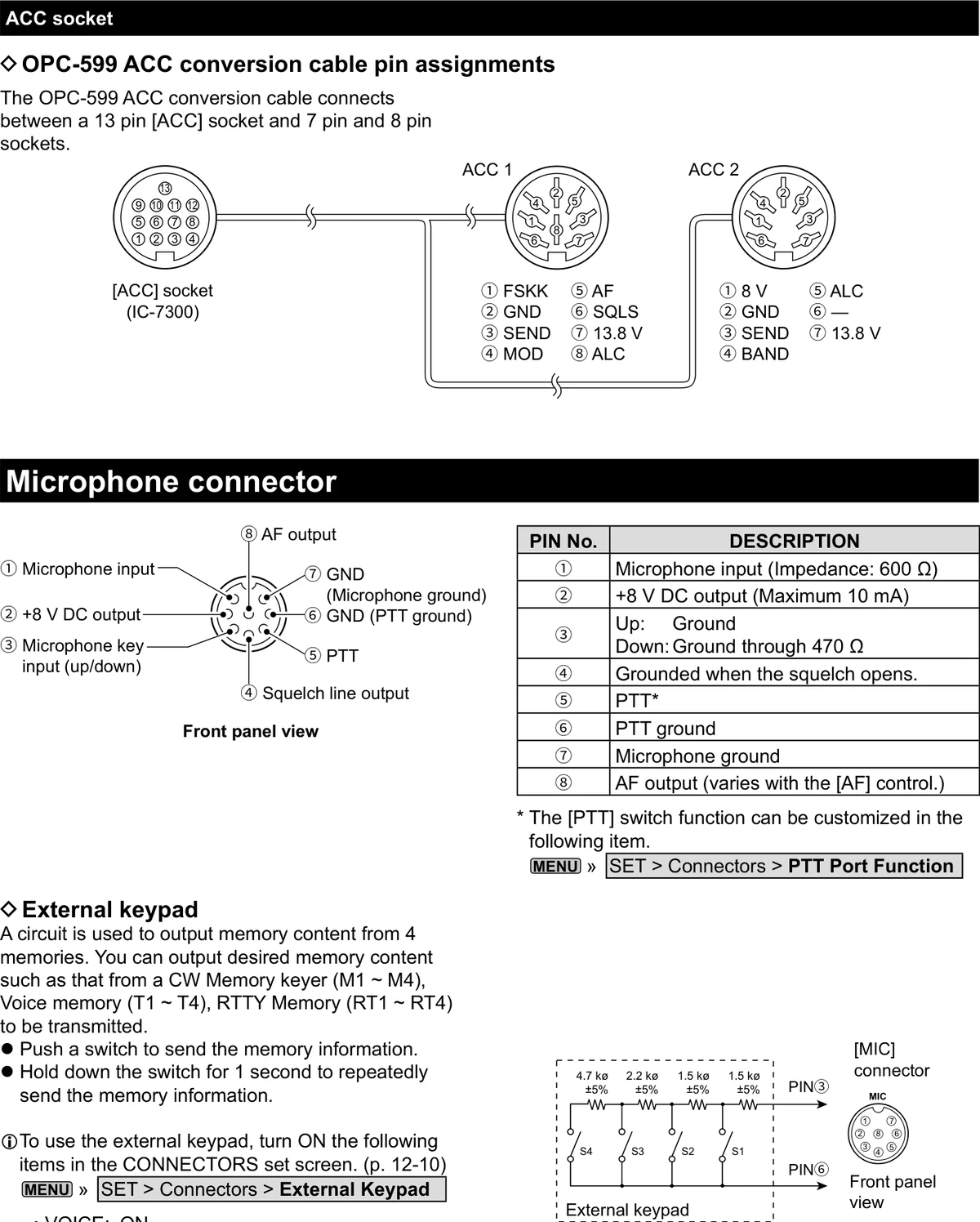
OPC-599 ACC 转接线用于在 13 针 [ACC] 插座与 7 针、8 针插座之间转接。
The OPC-599 ACC conversion cable connects between a 13 pin [ACC] socket and 7 pin and 8 pin sockets.
| ACC 1 引脚号ACC 1 PIN No. | 名称NAME | ACC 2 引脚号ACC 2 PIN No. | 名称NAME |
|---|---|---|---|
| ① | FSKK | ① | 8 V |
| ② | GND | ② | GND |
| ③ | SEND | ③ | SEND |
| ④ | MOD | ④ | BAND |
| ⑤ | AF | ⑤ | ALC |
| ⑥ | SQL S | ⑥ | — |
| ⑦ | 13.8 V | ⑦ | 13.8 V |
| ⑧ | ALC |
图中标注:[ACC] socket(IC-7300)、ACC 1、ACC 2。
Figure labels: [ACC] socket (IC-7300), ACC 1, ACC 2.
18-3话筒插座Microphone connector
| 引脚号PIN No. | 说明DESCRIPTION |
|---|---|
| ① | 话筒输入(阻抗:600 Ω)Microphone input (Impedance: 600 Ω) |
| ② | +8 V DC 输出(最大 10 mA)+8 V DC output (Maximum 10 mA) |
| ③ | 上:接地 下:经 470 Ω 接地Up: Ground Down: Ground through 470 Ω |
| ④ | 静噪开启时接地。Grounded when the squelch opens. |
| ⑤ | PTT*PTT* |
| ⑥ | PTT 地PTT ground |
| ⑦ | 话筒地Microphone ground |
| ⑧ | AF 输出(随 [AF] 旋钮变化)AF output (varies with the [AF] control.) |
提示 NOTENOTE
* [PTT] 开关功能可在下列项目中自定义。
MENU » SET > Connectors > PTT Port Function
* The [PTT] switch function can be customized in the following item.
MENU » SET > Connectors > PTT Port Function
18-3外接键盘External keypad
该电路用于输出 4 组存储内容。您可以把所需的存储内容调出发射,例如 CW 存储电键(M1 ~ M4)、语音存储(T1 ~ T4)、RTTY 存储(RT1 ~ RT4)。
A circuit is used to output memory content from 4 memories. You can output desired memory content such as that from a CW Memory keyer (M1 ~ M4), Voice memory (T1 ~ T4), RTTY Memory (RT1 ~ RT4) to be transmitted.
• 按下开关即发送该存储信息。
• 按住开关 1 秒,则连续重复发送该存储信息。
• Push a switch to send the memory information.
• Hold down the switch for 1 second to repeatedly send the memory information.
提示 NOTENOTE
要使用外接键盘,请在 CONNECTORS 设置屏幕中将下列项目设为 ON(见 12-10 节)。
MENU » SET > Connectors > External Keypad
• VOICE: ON
• KEYER: ON
• RTTY: ON
To use the external keypad, turn ON the following items in the CONNECTORS set screen. (p. 12-10)
MENU » SET > Connectors > External Keypad
• VOICE: ON
• KEYER: ON
• RTTY: ON
说明 NOTENOTE
外接键盘非 Icom 随机提供(需用户自备)。
The External keypad is not supplied by Icom. (User supplied)
| 项目Item | 标注值Labeled value |
|---|---|
| S1 / S2 / S3 / S4 | 外接键盘开关(经 [MIC] 连接器的 PIN③ 与 PIN⑥ 接入)External keypad switches (connected via PIN③ and PIN⑥ of the [MIC] connector) |
| S4 串联电阻 | 4.7 kΩ ±5%4.7 kΩ ±5% |
| S3 串联电阻 | 2.2 kΩ ±5%2.2 kΩ ±5% |
| S2 串联电阻 | 1.5 kΩ ±5%1.5 kΩ ±5% |
| S1 串联电阻 | 1.5 kΩ ±5%1.5 kΩ ±5% |
18-4KEY 插孔KEY jack
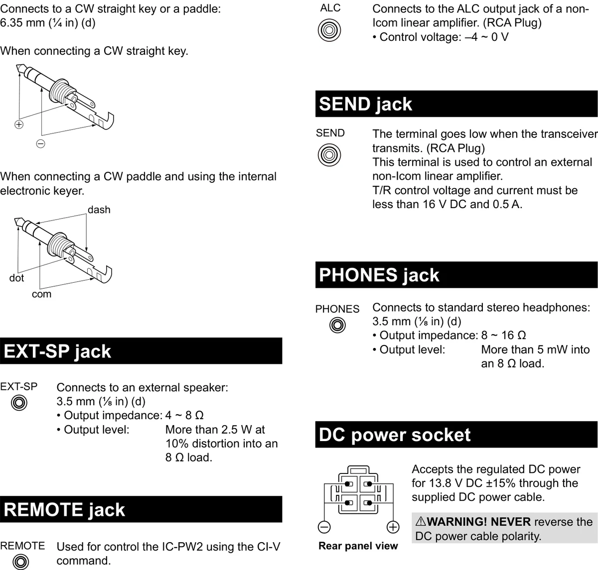
用于连接 CW 直键或桨式拍发器:6.35 mm(¼ in)(d)
Connects to a CW straight key or a paddle: 6.35 mm (¼ in) (d)
连接 CW 直键时。
When connecting a CW straight key.
图中标注:⊕、⊖(com)。
Figure labels: ⊕, ⊖ (com).
连接 CW 桨式拍发器并使用内置电子电键时。
When connecting a CW paddle and using the internal electronic keyer.
图中标注:dash(划)、dot(点)、com(公共端)。
Figure labels: dash, dot, com.
18-4EXT-SP 插孔EXT-SP jack
用于连接外接扬声器:3.5 mm(⅛ in)(d)
• 输出阻抗:4 ~ 8 Ω
• 输出电平:8 Ω 负载、10% 失真时大于 2.5 W。
Connects to an external speaker: 3.5 mm (⅛ in) (d)
• Output impedance: 4 ~ 8 Ω
• Output level: More than 2.5 W at 10% distortion into an 8 Ω load.
18-4REMOTE 插孔REMOTE jack
用于通过 CI-V 指令控制 IC-PW2。3.5 mm(⅛ in)(d)
Used for control the IC-PW2 using the CI-V command. 3.5 mm (⅛ in) (d)
18-4ALC 插孔ALC jack
连接到非 Icom 线性放大器的 ALC 输出插孔。(RCA 插头)
• 控制电压:-4 ~ 0 V
Connects to the ALC output jack of a non-Icom linear amplifier. (RCA Plug)
• Control voltage: -4 ~ 0 V
18-4SEND 插孔SEND jack
收发信机发射时,该端子为低电平。(RCA 插头)
该端子用于控制外接的非 Icom 线性放大器。
T/R 控制电压与电流必须小于 16 V DC 和 0.5 A。
The terminal goes low when the transceiver transmits. (RCA Plug)
This terminal is used to control an external non-Icom linear amplifier.
T/R control voltage and current must be less than 16 V DC and 0.5 A.
18-4PHONES 插孔PHONES jack
用于连接标准立体声耳机:3.5 mm(⅛ in)(d)
• 输出阻抗:8 ~ 16 Ω
• 输出电平:8 Ω 负载时大于 5 mW。
Connects to standard stereo headphones: 3.5 mm (⅛ in) (d)
• Output impedance: 8 ~ 16 Ω
• Output level: More than 5 mW into an 8 Ω load.
18-4DC 电源插座DC power socket
通过随机附带的 DC 电源线接入稳压 13.8 V DC ±15% 直流电源。
Accepts the regulated DC power for 13.8 V DC ±15% through the supplied DC power cable.
图中标注:Rear panel view(后面板视角)、⊖(负极)、⊕(正极)。
Figure labels: Rear panel view, ⊖, ⊕.
警告 WARNINGWARNING
切勿反接 DC 电源线的极性。
NEVER reverse the DC power cable polarity.